

Busbar Insulator Factory: Essential Guide to Quality Manufacturing and Electrical Safety
2026-11-02
Most electrical failures don't start with a dramatic short circuit—they start on the factory floor, with a busbar insulator that wasn't made to handle real working conditions. This guide takes you inside quality manufacturing for busbar insulators and the electrical safety practices that separate dependable products from risky ones. If you're comparing suppliers or just want to understand what should be tested before shipment, the next few sections are for you. MOLDVOLT has been on the side of rigorous manufacturing from the start.
Raw Polymer Compounds That Resist Surface Tracking
Surface tracking remains one of the most insidious failure modes in high-voltage insulation, where carbonized conductive paths creep across a polymer surface under contamination and electrical stress. Raw polymer compounds engineered to resist this degradation typically blend a base resin—often polyolefin, silicone, or epoxy—with carefully selected fillers such as alumina trihydrate, silica, or magnesium hydroxide. These mineral additives do more than stiffen the matrix; they disrupt the formation of continuous carbon tracks by absorbing heat, releasing water vapor, and creating a ceramic-like barrier at the erosion zone. The result is a compound that can withstand repeated dry-band arcing without developing a permanent short circuit.
Formulation choices matter far beyond filler loading. The polymer backbone itself must survive partial discharge and UV exposure without excessive chain scission, because broken molecular chains accelerate carbonization. Silicone-based raw compounds naturally produce a non-conductive silica residue when degraded, which is one reason they dominate outdoor insulation. However, even commodity resins can be modified with tracking-resistant packages that shift the failure mode from igniting a conductive path to gradual, localized erosion. The key is balancing hydrophobicity, thermal stability, and filler dispersion so that no single weak phase becomes a nucleation point for carbon growth.
From a processing standpoint, raw tracking-resistant compounds demand tighter control over viscosity and cure kinetics than standard grades. Poor dispersion of mineral fillers creates local hot spots where tracking initiates early, while over-cured regions become brittle and micro-crack under thermal cycling. Manufacturers often tailor the compound's melt flow and crosslink density to match the intended molding or extrusion process, ensuring the finished insulator retains a uniform resistance layer from surface to core. This combination of material selection, filler synergy, and process discipline is what separates a compound that merely passes a laboratory tracking test from one that performs reliably for decades in polluted, wet, or coastal environments.
Molding Pressures That Eliminate Internal Voids
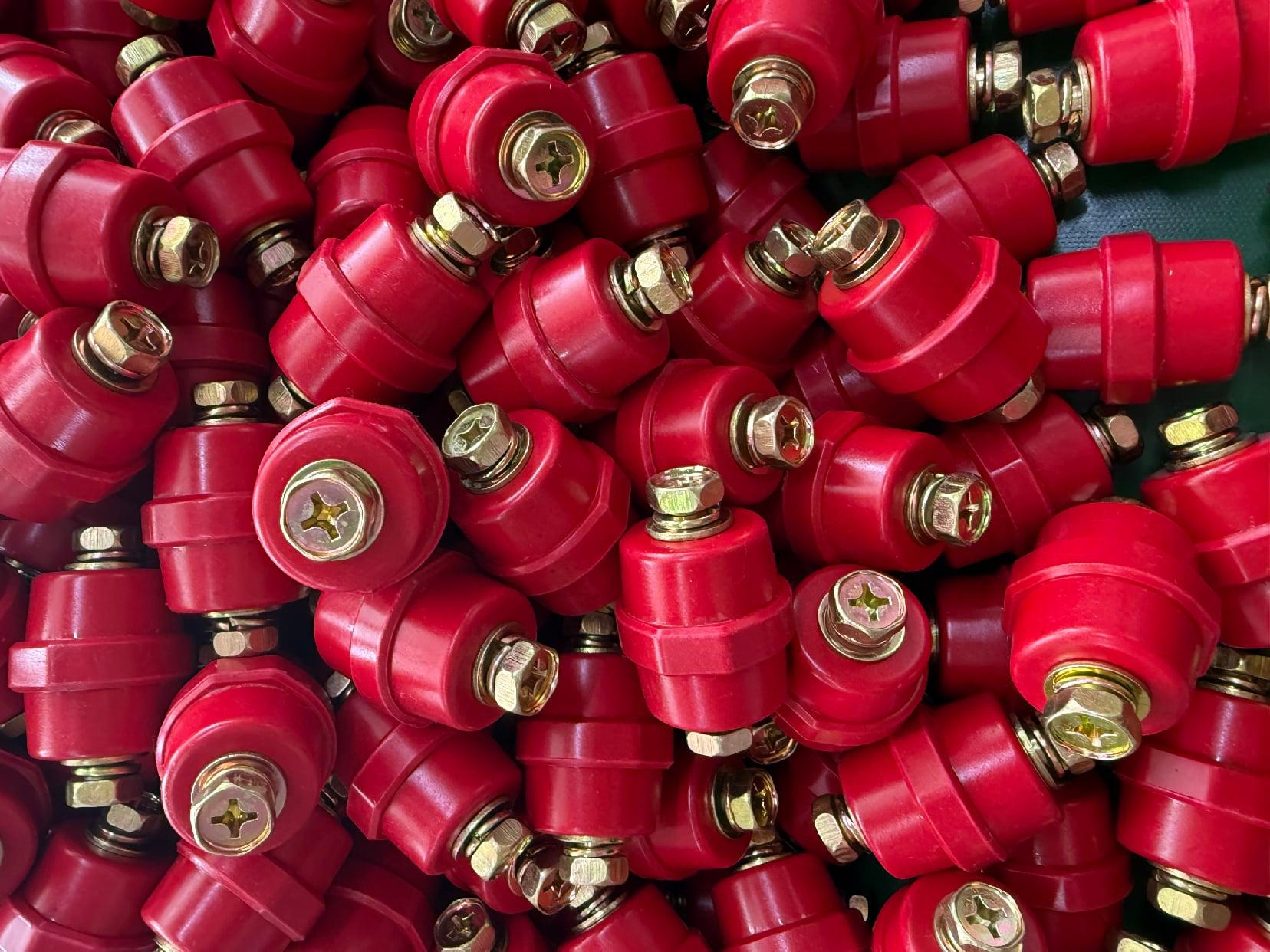
Voids rarely appear because the resin is bad; they appear because trapped air or volatiles have nowhere to go when the mold closes. The right molding pressure acts less like a brute force and more like a steady hand that keeps every layer in contact while the material softens. By maintaining a consistent compressive load across the cavity, you force small gas pockets to migrate toward the edges or into dedicated vent channels instead of staying locked inside the part.
A single high-pressure spike often does more harm than good, especially in thick sections or complex geometries. The better approach is to raise pressure in stages: a moderate initial squeeze lets the resin flow and wet out fibers, then a higher hold pressure collapses remaining micro-voids before gelation. On several thermoset laminates, moving from 0.3 MPa to 0.7 MPa at the right viscosity window reduced internal porosity from visible bubbles to near zero without starving the laminate of resin.
Pressure also works best when the tooling gives air an escape route. Shallow vents, breathable edge dams, or vacuum-assisted molds lower the pressure needed to achieve a void-free cross-section. With a well-designed vent path, even a modest 0.5 MPa press load can produce parts that section cleanly with no pinholes, while a poorly vented mold at 1 MPa may still trap gas in the center.
Electrical Testing Beyond the Standard Flashover Check
A standard flashover check tells you if insulation can survive a quick high-voltage spike, but it says almost nothing about the slow degradation already underway inside the dielectric. Moisture absorption, thermal aging, and microscopic voids often stay hidden until a routine flashover test finally exposes them as a full breakdown. By then, the asset has already been running on borrowed time.
More revealing diagnostics start with insulation resistance and polarization index measurements, which track how current leaks through the bulk material over a ten-minute window. A healthy insulation shows rising resistance as absorption currents decay; a falling or flat curve points to contamination or water trees. Dielectric dissipation factor and partial discharge testing go further, mapping energy loss and locating the exact spot where tiny internal arcs are chewing away at the insulation.
Field data regularly shows transformers and switchgear passing flashover checks yet failing on tan delta or partial discharge thresholds, alerting crews to moisture in cellulose or voids in epoxy bushings before a catastrophic fault. Replacing guesswork with these layered electrical tests shifts maintenance from reactive to condition-based, keeping aging infrastructure in service longer without gambling on a single dramatic arc test.
Designing Creepage Paths for Polluted Environments
Surface contamination changes how insulation behaves long before visible damage appears. In polluted environments, dust, salt spray, or industrial residues settle on insulating surfaces and combine with humidity to form a conductive film. This film shortens the effective creepage distance between conductors, allowing leakage current to flow across the surface. Designers often respond by increasing geometric spacing, but that alone rarely solves the problem if the contamination layer is continuous. The real task is to interrupt that layer or slow its formation.
One practical approach is to shape the surface so moisture and residue do not collect in uninterrupted paths. Ribs and grooves create longer, more tortuous routes for tracking currents while also shedding water more effectively. Vertical surfaces tend to stay cleaner than horizontal ones, and sheltered areas under ledges or inside housings can reduce deposition. Material selection matters just as much: polymers with high comparative tracking index values resist carbonization when micro-arcs occur, which keeps local damage from turning into a permanent conductive trace.
For severe outdoor or marine conditions, designers sometimes apply conformal coatings or use hybrid insulation systems, but these add manufacturing steps and require inspection for pinholes and adhesion loss. A better starting point is to derate clearance requirements based on the expected pollution degree and then verify performance through salt-mist or dust-cycle testing. Observations from failed units often show that tracking starts at sharp edges or narrow gaps where contamination builds up first, so rounding those features and opening the spacing can yield more improvement than a uniform increase in creepage distance.
Thermal Cycling Without Developing Microcracks
Repeated thermal cycling usually punishes brittle materials by nucleating tiny cracks at grain boundaries or phase interfaces. The real challenge is to let expansion and contraction happen without letting those localized strain mismatches accumulate into fractures. One practical route is to engineer a microstructure that tolerates small plastic accommodations instead of purely elastic stress buildup—fine-grained matrices with dispersed compliant phases can absorb local deformation before it reaches a critical intensity.
Another frequently overlooked factor is the ramp rate and dwell profile. Slow, controlled transitions allow creep and diffusional relaxation to redistribute stresses that would otherwise spike at corners or interfaces. In layered structures, matching coefficients of thermal expansion between adjacent materials, or introducing graded interlayers, prevents the sharp discontinuities that typically initiate microcracks. Components that survive thousands of cycles often combine this material-side design with thermal management so the entire volume changes temperature more uniformly.
Batch Traceability From Mixing Room to Final Assembly
In the mixing room, every raw material drum carries a unique lot identifier that gets scanned or keyed into a weigh station before any powder or liquid enters the mixer. That action creates a mix batch record with a timestamp, operator ID, and the specific blender used. Operators also note any manual additions or reworks, because these small deviations often matter later when a viscosity or cure issue shows up on the line.
Once mixing is complete, the batch number travels with the compound, either on a printed label attached to a tote, through an RFID tag on a returnable container, or in some older plants on a paper traveler that gets signed at each handoff. Line-side material handlers confirm the batch number against the work order before loading it into dispensing equipment. This check prevents a wrong batch from being consumed in a subassembly that could then contaminate a full shift of production.
At final assembly, the mix batch identifier is linked to the serial number of each finished unit, usually through a scan event or a build record. That linkage turns a simple list of raw material lots into a true traceability chain. If a mixing room error is discovered days or weeks later, the team can pull every serial number that used the affected batch and quarantine only those units, instead of shutting down the entire line or issuing a broad recall.
FAQ
Epoxy resin, porcelain, and cycloaliphatic resin dominate the floor. Epoxy offers high tensile strength and is easy to cast into complex shapes, while porcelain gives superior resistance to surface tracking in polluted environments. Cycloaliphatic resin hits a middle ground with good UV stability and lighter weight for indoor switchgear.
The insulator is placed between electrodes in a shielded room, and voltage is ramped to a set multiple of the rated line-to-ground value. Sensors pick up high-frequency current pulses caused by internal voids, and any reading above a few picocoulombs flags the part for rejection. This non-destructive method catches defects that would otherwise lead to long-term breakdown.
Creepage distance is the path along the insulator surface between live parts, and contamination like dust or moisture can make that surface conductive. A longer creepage distance reduces the chance of a tracking arc under humid or dirty conditions. Air gap clearance alone does not account for surface pollution, so factories extend sheds or ribs to meet specific pollution class ratings.
Resin is mixed under vacuum to remove dissolved gases, then poured into heated molds at a controlled low viscosity. The mold is rotated or vibrated briefly to let trapped air rise to a vent, and pressure gelation is applied to lock the material without shrinkage cavities. After curing, X-ray or ultrasonic inspection confirms there are no hidden voids.
Samples are placed in a chamber that alternates between extreme cold and rated operating heat, often -40°C to 130°C, with soak times of several hours per cycle. After 50 to 200 cycles, the insulator must show no cracks, delamination, or loss of mechanical strength. This test mimics the stress from repeated load changes and outdoor temperature swings.
The semi-conductive glaze spreads electric field stress evenly across the surface, reducing local corona discharge and radio interference. It also slightly warms the surface through a tiny leakage current, which helps evaporate moisture and condensation in humid environments. Factories use this on insulators for high-voltage outdoor busbars where corona control matters.
They increase the core diameter and use flexible mounting flanges that absorb lateral movement without transferring stress to the porcelain or resin body. Finite element analysis simulates earthquake loads, and the insulator may include an internal fiberglass rod for tensile strength. Final prototypes undergo shake-table testing per IEEE 693 to verify performance.
Inspect for hairline cracks, chalking, or discoloration that indicates surface erosion. Use a non-contact infrared thermometer to spot any hot spots that suggest internal partial discharge. Clean with deionized water and a soft cloth when contamination levels rise, avoiding abrasive tools that could scratch the glaze or epoxy surface.
Conclusion
Quality in a busbar insulator factory starts well before the first molding cycle. Raw polymer compounds are selected specifically for their resistance to surface tracking, which helps prevent conductive carbon paths in polluted or humid service conditions. During molding, controlled pressures are used to squeeze out entrapped air and eliminate internal voids that could later become partial discharge sites. Instead of relying only on a routine flashover check, the test line adds partial discharge, insulation resistance, and thermal stability measurements to catch hidden defects. For installations in coastal or industrial zones, creepage distances are deliberately extended and shaped to shed contamination, keeping leakage current under control. This upfront material choice directly reduces long-term maintenance and unexpected flashover risks.
Thermal cycling is another critical step: insulators are repeatedly ramped between hot and cold extremes, then inspected for microcracks that could weaken the structure over time. Every batch carries traceable records from the mixing room through molding, curing, testing, and final assembly. If a field issue ever appears, the factory can pull the exact compound lot, press settings, and inspection data in minutes. Suppliers and production logs stay linked to each serial number, so every installed insulator has a clear manufacturing history. That kind of end-to-end visibility is not just paperwork; it is what keeps electrical safety repeatable across thousands of units.
Contact Us
Contact Person: Hellen
Email: [email protected]
Tel/WhatsApp: 86-13634205622
Website: https://www.voltcabinet.com