

Custom Sliding DU Bushings – A Complete Guide to Materials, Design, and Applications
2026-11-16
When a standard bushing fails under heavy loads or aggressive motion, the solution often lies in the details—material choice, surface finish, and the subtle art of custom sizing. XIAYI has spent years refining custom sliding DU bushings for applications where off-the-shelf parts simply won't survive. In this guide, we break down what actually matters: from PTFE-lined steel backing to the tolerances that keep a machine running quietly at 3 a.m. If you've ever wondered why one bushing lasts a decade and another dies in a week, the answer is probably on the next page.
The Core Structure: How the PTFE-Lead Layer Reduces Friction Without External Lubrication
At the heart of this design lies a PTFE matrix infused with finely dispersed lead particles. PTFE already possesses one of the lowest coefficients of friction among solid materials, but its tendency to creep under load limits standalone use. The lead filler counteracts this by increasing compressive strength and promoting a more uniform transfer film on the mating surface. This self-generated film acts as a solid lubricant, eliminating the need for oil or grease even in dry-running conditions.
During operation, microscopic asperities on the counterpart shear off small amounts of the PTFE-lead composite. These particles smear across the contact zone, creating a low-shear interface that separates the two metal surfaces. Because lead has a natural affinity for both PTFE and common shaft materials like steel, the transfer layer adheres firmly and replenishes itself continuously. The result is a stable, low-friction regime that persists across a wide range of sliding speeds and temperatures.
Unlike externally lubricated systems that depend on a fluid film, this structure thrives where contamination or maintenance access is limited. The lead content also helps dissipate frictional heat, preventing localized hot spots that could degrade the polymer. By combining PTFE's inherent slipperiness with lead's load-bearing and film-forming properties, the core layer achieves reliable friction reduction without any additional lubricant.
Steel Backing and Sintered Bronze: Why Material Pairing Dictates Load Ratings
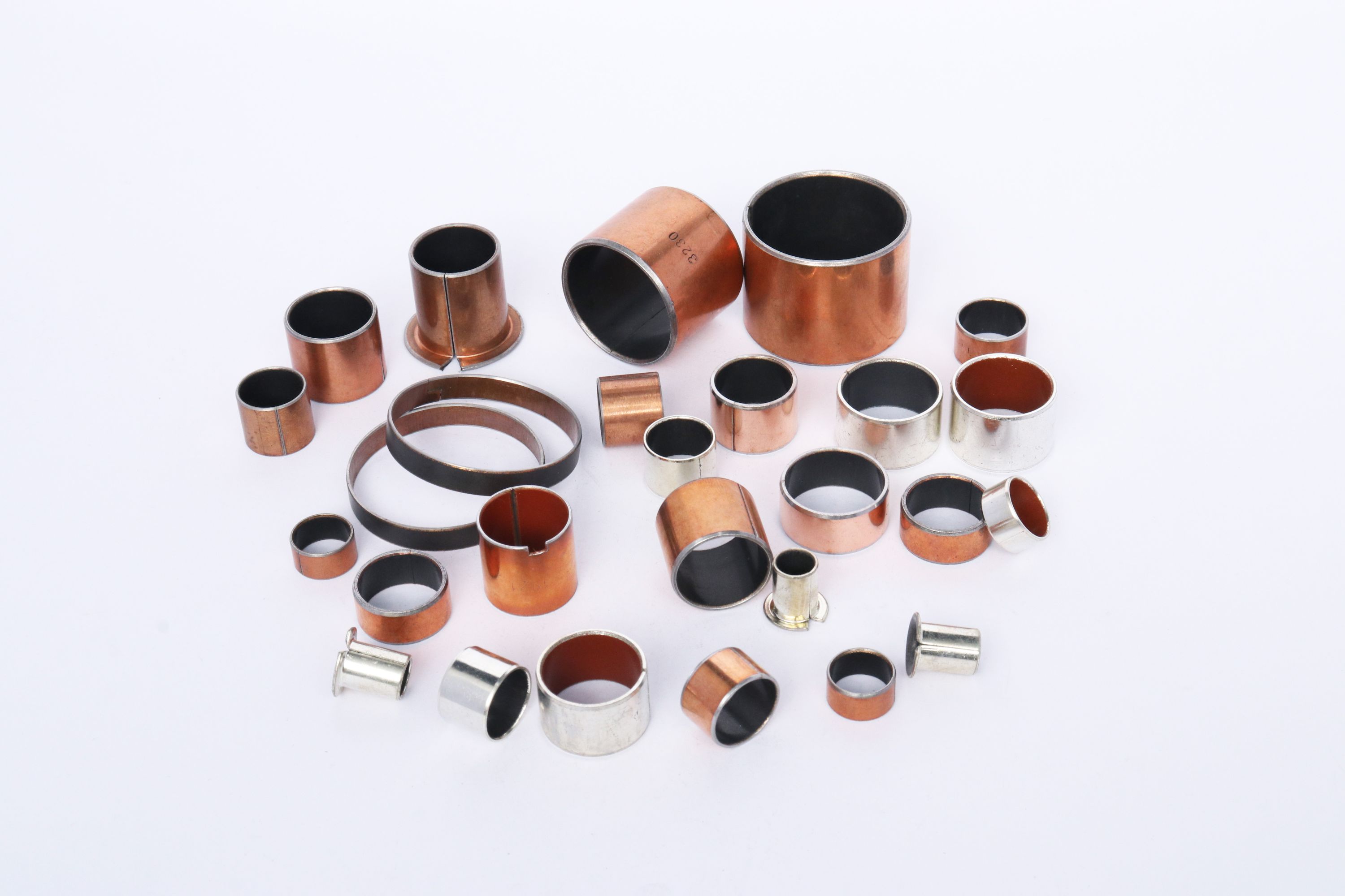
Load ratings for plain bearings rarely come down to a single material property. They emerge from how two layers behave together under stress. Steel backing provides the structural backbone, resisting deformation when radial or axial forces spike. Sintered bronze, bonded to that steel, handles the sliding surface and retains lubricant within its porous network. Mistake the pairing for a simple lamination, and you miss the reason a modest wall thickness can support surprisingly high loads.
The steel layer sets the fatigue limit. If backing yields, the bronze lining cracks or separates, no matter how dense its powder structure. Conversely, a thick bronze layer on thin steel brings little benefit because load distribution becomes uneven. The interface between the two layers matters just as much; poor bonding creates stress concentrations that shorten service life under cyclic loading. Engineers tune the bronze porosity and steel hardness together, aiming for a balance where neither component dictates failure prematurely.
Temperature complicates the picture further. Steel expands less than bronze, so a bearing running hot may see the lining try to grow faster than its backing. That mismatch introduces internal shear at the bond line. Material pairing choices, such as using low-tin bronze or adding a copper interlayer, directly influence how much load the assembly tolerates before spalling or seizure occurs. In practice, load ratings given in catalogs reflect not isolated test data but the empirical behavior of this steel-bronze system under realistic conditions.
Getting the Fit Right: Custom Tolerances and Bore Preparation for Sliding Bushings
Sliding bushings live and die by the clearance between their outer diameter and the housing bore. Most off-the-shelf units assume a standard H7 bore, but real-world assemblies rarely fit that neatly into a catalog. When you need a press fit that won't creep under reversing loads or a slip fit that allows thermal expansion without binding, you have to move beyond generic numbers. Custom tolerances let you dial in exactly how the bushing seats in the bore—whether that's a light interference to lock it in place or a controlled gap for easy field replacement. The key is to match the tolerance band to the actual material pair, operating temperature range, and load direction, not just copy a value from a previous project.
Bore preparation is where most sliding bushing installations go sideways. Even a perfectly machined bushing will fail early if the housing bore has a poor surface finish, taper, or out-of-round condition. For a reliable press fit, the bore should be honed or fine-bored to a surface roughness of Ra 0.8–1.6 µm, with no visible spiral tool marks that can channel lubricant away. Chamfer the entry edge at 15–20 degrees to a depth slightly less than the bushing's corner radius—this prevents shaving the bushing OD during installation. If you're working with a split housing or a thin-wall bore, consider a stepped preparation: a short lead-in diameter at the upper tolerance limit, followed by the main bore at the lower limit, so the bushing compresses gradually instead of hitting a sharp step.
Once the bore is ready and the custom tolerance is locked in, test the fit before committing to full assembly. Use a dummy bushing or the actual part with a light coating of assembly lubricant, and measure the push-in force with a hand press and load cell. A sudden drop or spike in force usually means a burr, taper, or misalignment that wasn't caught by a go/no-go gauge. Remember that the bore will change shape after the bushing is installed—the bushing's ID shrinks as the OD is compressed, so your final running clearance must be calculated from the as-installed dimension, not the free state. If you're running a sliding application with frequent starts and stops, tighten the bore tolerance slightly and increase the surface finish quality to reduce fretting at the interface. Small adjustments here pay off in longer bushing life and quieter operation.
Designing for Edge Loading and Misalignment in Real-World Assemblies
In many assemblies, perfect alignment is more of an ideal than a reality. Tolerances from machining, thermal expansion, and assembly sequence can push loads toward the edges of mating parts. This edge loading often concentrates stress in a narrow band, accelerating wear or causing brinelling in bearings, fretting in bolted joints, or plastic deformation in softer materials. Rather than assuming loads distribute evenly, designers need to map how misalignment shifts the contact patch and what local pressures result.
One practical approach is to introduce compliance where it matters. Slotted holes, spherical washers, or self-aligning bushings can give the joint enough freedom to settle without fighting itself. If the structure must remain rigid, then controlling the tolerance stack becomes critical—specifying flatness, perpendicularity, and position in a way that anticipates worst-case tilt. A useful habit is to run a quick hand calculation of the edge stress under maximum allowable misalignment before committing to a material or surface treatment.
Validation matters just as much as the initial design. Prototype assemblies often fit together by hand, masking the variation that appears in production. Testing with deliberately offset or canted parts helps reveal whether the design can tolerate real-world scatter. In some cases, adding a local relief or a slight crown to a contact surface is enough to move the peak pressure away from the edge and back toward the center, making the assembly far less sensitive to the inevitable misalignment of production and service.
Application Spotlights: Where Custom DU Bushings Outperform Roller Bearings
In low-speed, high-load pivot joints on agricultural tillage equipment, custom DU bushings handle oscillating motion that would quickly brinell standard roller bearings. The steel backing carries the load while the PTFE-lead lining provides a dry lubricant film, so there is no need for a full rotation to distribute grease. Farmers routinely see these bushings outlast needle rollers in the same clevis positions, especially where reversing loads and vibration are constant.
Packaging machines with cramped cam follower arms are another spot where DU bushings make more sense than roller bearings. A custom thin-wall DU sleeve fits into the same bore as the original needle bearing but needs no seals, no lubrication fittings, and no extra axial width. For designers trying to shave grams off a reciprocating assembly, that reduction in parts count and the elimination of a grease path often outweigh the lower speed rating of a plain bushing.
Marine steering linkages and food processing conveyors share a common problem: washdown water and abrasive fines. Custom DU bushings with a corrosion-resistant backing (such as tin-plated steel or a stainless shell) survive salt spray and daily hose-downs without pitting, while exposed roller bearings would rust and bind. The bushing's embedded solid lubricants also mean no grease purge into the product zone, which matters a lot in sanitary designs.
Extending Service Life: Break-In Procedures and Wear Monitoring
A proper break-in rarely means running a component gently. It means deliberately cycling loads to help mating surfaces develop a work-hardened, oil-retaining texture without scuffing. For many gearboxes, that translates to six to eight short runs at 60–70% of rated torque, with a full cool-down between each. Skipping this step or treating it as a formality often leaves microscopic high spots that later become crack initiation sites.
Wear monitoring works best when you track trends rather than isolated numbers. A single spike in iron or copper from an oil sample tells you almost nothing; three consecutive samples with a steepening slope do. Pair that with simple clearance measurements or vibration spectra taken at the same operating temperature. If the clearance growth rate doubles after the first 100 hours, you are not looking at normal bedding-in—you are looking at the early signs of misalignment or lubricant starvation.
The real payoff comes from connecting break-in records to long-term wear data. Note the exact load steps, temperatures, and any unusual noise during the first week. Later, when a wear trend begins to rise, you can compare it against that baseline instead of a generic manufacturer curve. Machines that had a rushed break-in often show a characteristic early plateau in wear metals, followed by a sudden acceleration. Catching that transition before it reaches critical clearance is what turns routine servicing into genuine life extension.
FAQ
A DU bushing is a self-lubricating plain bearing built around a steel shell, a porous bronze sinter layer, and a PTFE-based liner. The custom aspect means you control dimensions, tolerances, groove patterns, and often the liner formulation. Standard bushings force you to fit your design around available sizes, but custom versions let you match a specific shaft diameter, wall thickness, or unusual load case without redesigning the housing.
The backing is usually low-carbon steel, giving the bushing enough structural strength to hold its shape under press-fit installation. Next comes a layer of sintered bronze, which acts as a heat conductor and a mechanical anchor for the liner. The running surface is a PTFE compound, often blended with fillers like lead, molybdenum disulfide, or ceramics to tune wear resistance and friction. Some lead-free versions swap in polymers or mineral fillers for regulations or food-contact needs.
Start with the actual operating load, speed, and whether the motion is oscillating, rotating, or linear. Shaft hardness and finish matter because the PTFE liner transfers material to the shaft during break-in. You also need to decide on wall thickness, fitting method, and whether you want features like lubrication grooves, flanges, or locating notches. Temperature range is critical since standard liners lose performance above roughly 250°C unless specified otherwise.
Higher loads call for a thicker steel backing and sometimes a denser bronze layer to prevent deformation. At higher surface speeds, you generate more frictional heat, so a liner with better thermal conductivity or a modified PTFE blend helps avoid premature wear. Low-speed, high-load situations often benefit from fillers like graphite or MoS₂, while high-speed, light-load jobs do fine with standard PTFE compounds.
Yes, DU-style bushings are designed to run dry for their entire service life under normal conditions. The PTFE liner provides a low-friction transfer film on the shaft, so grease or oil is not required. That said, if you operate in contaminated environments or at the limits of load and speed, a little external lubrication can extend life. But you should not rely on it as a design requirement unless your conditions are unusually harsh.
Hardened steel shafts work best, typically with a surface hardness of HRC 45 or higher. Stainless steel can work but may need a slightly smoother finish to minimize liner wear. Aim for a surface roughness around Ra 0.2–0.4 µm on the running area. Softer shafts, like mild steel or aluminum, are generally poor choices because they wear quickly and can tear the PTFE transfer film.
They shine in applications where space is tight, dirt or dust is present, and maintenance access is poor. Think agricultural pivots, construction equipment joints, automotive seat mechanisms, and industrial textile machinery. Unlike ball bearings, they do not need seals or relubrication, and unlike solid polymer bushings, they handle much higher edge loads and offer better dimensional stability under press-fit.
Provide the exact housing bore diameter after machining, not a nominal size. Specify the bushing's outside diameter with press-fit allowance, usually between 0.05 and 0.15 mm interference depending on housing material. Give the finished inside diameter after installation, because the bore shrinks slightly when pressed in. If you need a running clearance, state your target shaft diameter and let the bushing maker calculate the post-installation ID. Also mention chamfer requirements and any orientation features.
Conclusion
Custom sliding DU bushings rely on a three-layer architecture that quietly solves lubrication problems: a steel backing provides structural rigidity, a porous sintered bronze interlayer anchors the lining, and a PTFE-lead overlay creates a low-friction running surface that transfers material to the shaft during initial movement. This self-lubricating mechanism eliminates the need for external grease or oil, which is why these bushings thrive in hard-to-reach or maintenance-averse assemblies. But the real performance ceiling is set by the material pairing. The steel backing resists deformation under static or oscillating loads, while the bronze layer cushions and distributes stress; mixing a thin steel shell with a dense bronze matrix can dramatically lower load ratings, so custom designs must balance thickness and porosity for the expected PV values.
Fit and preparation determine whether that material potential survives in the real world. Custom tolerances typically call for an interference fit in the housing, and the bore must be cleaned, deburred, and sometimes honed to avoid high spots that tear the PTFE surface. Because sliding bushings cannot accommodate much angular misalignment, designers often relocate the bushing edge away from the load line or add a chamfer to soften edge loading. In applications like agricultural pivots, textile machinery, or low-speed hydraulic cylinders, these custom DU bushings outperform rolling-element bearings by tolerating dirt, eliminating relubrication, and cutting noise. Service life extends further with a short break-in period at reduced load and speed, followed by periodic wear checks—measuring radial clearance or tracking shaft surface finish gives early warning before the bronze layer becomes exposed.
Contact Us
Contact Person: Leela
Email: [email protected]
Tel/WhatsApp: 8613586885132
Website: https://www.xiayishockparts.com