

Custom Split Butterfly Valve: Key Design Considerations and Industrial Applications
2026-09-02
Engineers pushing for higher yields in hygienic, abrasive, or high-temperature processes often overlook one critical component: the valve. A custom split butterfly valve can eliminate dead zones, ease cleaning, and prevent cross-contamination—but only when the split design is tailored to real operating conditions. In this article, we explore the key design considerations and industrial use cases where AVM has delivered measurable improvements.
Matching Disc and Body Alloys to Aggressive Chemical Streams
Selecting disc and body alloys for aggressive chemical streams rarely comes down to a single chart lookup. The exact mix of acids, chlorides, oxidizers, and trace metals shifts how a material corrodes, and the disc and body do not see identical conditions. A body may sit in relatively stagnant flow while the disc faces higher velocity, turbulence, and repeated contact with the seat. That means the two components often need separate evaluations rather than a matched pair chosen from the same alloy family.
A common starting point is to match the body alloy to the bulk stream’s general corrosion behavior, then give the disc a grade with extra resistance to erosion-corrosion, pitting, or galling. For example, a body in Alloy 20 can handle many sulfuric acid streams, but the disc may require Hastelloy C-276 if chlorides or oxidizing contaminants are present. In wet chlorine or hot hydrochloric acid, titanium or zirconium might be used selectively, but only after checking for crevice attack at sealing surfaces. Dissimilar alloys can work well if their electrochemical potentials are close enough to avoid aggressive galvanic coupling.
Field experience and lab coupons still beat guesswork. Test the actual stream at operating temperature and pressure, including upset conditions like aeration or concentration spikes. Pay attention to impurities such as ferric ions, which can dramatically accelerate attack on otherwise resistant alloys. The goal is not to find the most expensive material, but to give the disc and body the specific corrosion mechanisms they will actually face.
Why Split Bodies Turn Valve Maintenance Into a One-Person Job
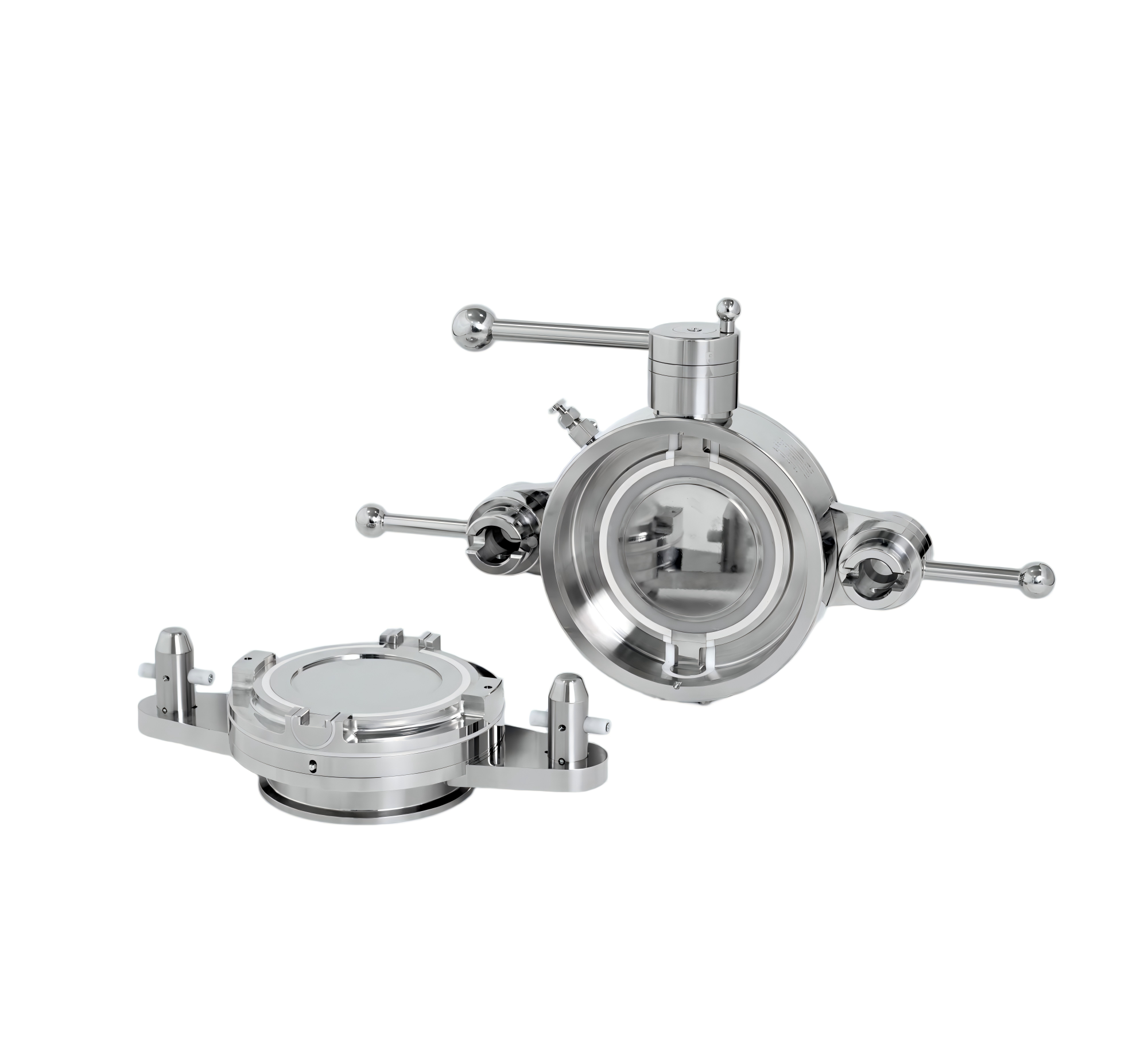
Most conventional valves demand a two-person crew because the body has to be lifted clear of the pipe or the actuator must be detached before any internal work starts. A split body changes that equation. The casing separates at a midline joint, so the trim, seat, and sealing elements stay accessible while the pipe connections remain untouched. One technician can unbolt the halves, slide the centre section out, and swap internals without fighting the weight of the entire assembly.
The real advantage shows up in tight mechanical rooms or elevated pipe racks. Instead of coordinating a hoist, a spotter, and a second set of wrenches, a single person can control the lift of just the split component. That reduces not only labour hours but also the chance of gasket misalignment when the valve goes back together. Since the two body halves stay aligned by the pipe itself, reassembly becomes a straightforward bolt-up task rather than a rigging exercise.
There is also a practical maintenance benefit: because the wear parts are exposed once the split is opened, inspections and replacements happen faster. A solo mechanic can carry the split section to a bench, rebuild it under good light, and return it to the line without shutting down neighbouring equipment or waiting for a second shift. The design effectively removes the main physical obstacle that used to make valve service a two-person minimum.
Soft Seats vs. Metal Seats for Abrasive Slurry Lines
Soft seats, typically made from elastomers like natural rubber or polyurethane, work by deforming around solid particles to maintain a tight seal. In abrasive slurry lines carrying fine sand or mill tailings at moderate velocities, this flexibility can actually help the valve survive longer than expected—the seat absorbs impact energy and rebounds. But once particle size increases or sharp-edged rocks enter the flow, soft seats get cut, torn, or washed out quickly. Replacement downtime becomes a regular headache.
Metal seats, often hardened alloys or ceramic-coated surfaces, resist cutting and erosion far better in coarse, high-velocity slurry. They don't conform to particles, so leakage rates are slightly higher, but they hold up under conditions that would destroy an elastomer in hours. The trade-off is cost and the need for precise machining. In practice, many abrasive slurry lines use a hybrid approach: a metal seat with a soft insert ring, or a soft seat protected by a hardened lip. The right choice comes down to particle size distribution, flow velocity, and how often you're willing to shut down for maintenance.
Manual or Automated? Matching Actuation to Process Control Needs
Every plant has a handful of valves that operators insist on keeping manual, even when logic says otherwise. The reason rarely shows up in a spec sheet: those valves sit in spots where human judgment still outperforms a controller. Think of a bypass line during startup, where an experienced hand feels the subtle resistance of a sticky plug before a sensor ever flags it. Matching actuation to process control isn't just about replacing muscle with motors; it's about asking which tasks genuinely benefit from automation and which ones would lose more than they gain.
Automated actuation shines when the process demands repetition, speed, or precise positioning that no operator can sustain. But choosing a pneumatic cylinder over an electric drive—or a simple solenoid over a modulating positioner—requires looking past the initial cost. A valve that cycles every ten seconds in a batch reactor has completely different wear patterns and failure modes than one that adjusts once a shift. Over-automating a low-cycle manual valve often introduces new failure points: air supply leaks, position feedback drift, and control loop tuning headaches that never existed when someone just turned a handwheel.
The real skill lies in reading the process, not the catalog. Start by mapping how often a valve moves, how critical its position is to product quality or safety, and what happens if it fails mid-stroke. A manual valve with a locking lever might be the perfect fit for an isolation point that changes twice a year, while a fully automated control valve with redundant positioners is overkill—and a maintenance burden. Conversely, leaving a high-frequency throttling valve to manual operation invites inconsistency and operator fatigue. The best plants don't automate everything; they automate where the process control need is sharpest, and leave the rest to well-trained hands.
Food-Grade Split Valves: Sanitary Design Without Gasket Crevices
The real advantage of a split valve in food processing isn't just the ability to separate two line sections—it's what disappears when the halves pull apart. Traditional sanitary valves rely on compressed elastomer gaskets, and over time those gaskets develop micro-crevices at the sealing face. Product residue, cleaning chemicals, and bacteria can work into these tiny gaps, creating a persistent contamination risk that routine CIP cycles often miss. A food-grade split valve replaces the gasket pocket with a precision-lapped metal-to-metal closure on the active side, while the passive side remains sealed during separation. The result is a contact surface with no recessed grooves or dead zones where media can collect.
This geometry also changes how operators approach cleaning and product changeover. Because there is no gasket crevice to trap material, rinse water and sanitizing agents flow across a continuously smooth surface, and drainability improves significantly. In dry processing environments—think infant formula, starches, or powdered flavors—the absence of crevices prevents hygroscopic buildup that can harden and flake off into subsequent batches. For allergen management, switching between recipes becomes less risky because the split valve design allows the product-contact faces to be inspected directly after separation, rather than hiding behind a gasket that must be pried out for verification.
Fitting Split Butterfly Valves Into Existing Pipe Racks and Skids
Retrofitting split butterfly valves into crowded pipe racks rarely goes as smoothly as the datasheets suggest. The real challenge begins with understanding how the existing support structure shares load paths, because adding even a slim valve assembly can shift vibration modes and expose weak anchor points. Instead of forcing a standard bracket, experienced crews often field-measure the gap between adjacent lines, then cut and weld custom saddles that cradle the valve body without transferring torque into the pipe itself.
Another overlooked step is sequencing the installation around live process lines. On skids where shutdown windows are tight, pre-assembling the split valve with its actuator and limit switches off-site saves hours, but only if the final orientation matches the available clearance. A practical trick is to mock up the valve footprint with a plywood template and test swing clearance for the handle or gear operator before any pipe is cold-cut. This catches interferences with cable trays, instrumentation tubing, and even accessibility for future lockout-tagout procedures.
Finally, consider thermal growth and maintenance access. Split butterfly valves are often chosen because they can be serviced in place, but that advantage disappears if the valve is buried behind a newly routed conduit or a stiffener plate. Leaving at least one full actuator width of clear space on the operator side, and adding a simple U-bolt guide on long vertical drops, keeps the valve from becoming a future bottleneck. Document any field modifications with photos and as-built notes, because the next team to touch that rack will thank you for not hiding the split line behind a support beam.
FAQ
The body is split along the shaft line, so the disc and seat can come out without dropping the valve from the pipe. Standard wafer or lug versions have a one-piece body, which means spreading flanges or taking out nearby spools. That difference alone makes split units popular in tight skids or places where downtime costs more than the valve. Reassembly does need care with the joint alignment, but the tradeoff is usually worth it.
Disc edge geometry, seat material hardness, and shaft sealing take priority. A scalloped or relieved disc edge can reduce shearing of solids, while a reinforced elastomer or metal seat handles erosion better than a standard liner. You also want internal clearances sized to avoid particle entrapment, and a shaft seal that prevents slurry from packing around the bearings.
It allows the valve internals to be serviced from one side without removing the entire body. The upper half of the body can be unbolted and lifted away, exposing the disc and seat. In cramped pipe galleries or skid-mounted equipment, this often cuts repair time by half compared with a wafer valve. The main caveat is that the split joint itself must be aligned carefully during reassembly to avoid leaks.
They are favored in dry bulk handling, pharmaceuticals, and food processing where clean breaks and easy washdown are needed. The split body allows quick inspection of product-contact surfaces, which helps maintain hygiene standards. They also work well in pneumatic conveying lines because the valve can be built with a full-bore port and minimal dead space, preventing material hang-up.
PTFE-lined seats with an energised lip seal tend to hold up better than thick elastomer liners because they reduce friction and wear. For high temperatures, a metal seat with a hard-faced disc edge can survive hundreds of thousands of cycles. The key is matching the seat's recovery rate to the actuation speed; soft seats may not spring back fast enough if the valve cycles every few seconds.
The body halves, disc, shaft, and seat all see different stresses. A stainless steel body might resist corrosion but gall under frequent assembly and disassembly, so you might choose a duplex or coated carbon steel for the body halves. The disc may need a harder face for particle impact, while the shaft requires both strength and compatibility with packing materials. Thermal expansion differences between these parts can cause binding if not accounted for.
Cycle frequency, failure position, and available services usually drive the decision. Manual actuation suits lines that are opened rarely and where the valve is within reach. Pneumatic actuators are common in washdown areas because they tolerate moisture and provide fast stroke times. Electric actuators give better position feedback and can operate without plant air, but they need careful specing for torque because a split-body valve's breakaway torque can rise after long idle periods.
A standard disc profile leaves a flat face to the flow, creating turbulence behind the shaft. A custom hydrofoil or contoured disc can smooth the flow path and cut pressure loss significantly in large ducts. Reducing the shaft diameter or using a two-piece shaft with a streamlined hub also helps. These changes are more involved to machine but pay off in fan energy savings on high-volume air or gas lines.
Conclusion
When specifying a custom split butterfly valve, the first critical step is matching the disc and body alloys to the actual chemical stream. Aggressive acids, chlorides, or oxidizing media demand high-nickel alloys or titanium, while standard stainless steels may fail within months. The split body design itself changes maintenance economics: a single technician can unbolt the two halves, remove the disc, and replace the seat without dropping the valve from the line or needing a second pair of hands. This is especially valuable in cramped pipe racks or skids where overhead clearance and access are limited, and where a wafer-style valve would require significant disassembly of adjacent piping.
For abrasive slurry lines, the choice between soft seats and metal seats hinges on particle size, velocity, and temperature. Soft PTFE or UHMWPE seats offer bubble-tight shutoff but wear quickly under sharp, high-velocity solids; metal seats handle erosion better but sacrifice some sealing. Actuation also matters—manual levers may be fine for occasional isolation, but automated electric or pneumatic actuators with positioners are necessary for throttling or remote process control. In food and pharmaceutical applications, split butterfly valves with sanitary clamp ends and crevice-free gasket designs eliminate bacterial harborage points, while still allowing rapid disassembly for CIP validation. Ultimately, a well-designed custom split butterfly valve balances alloy chemistry, seat geometry, actuation torque, and the physical constraints of the installation to deliver reliable isolation and control without turning routine maintenance into a multi-person project.
Contact Us
Contact Person: Ananda
Email: [email protected]
Tel/WhatsApp: 8619016718200
Website: https://www.wzaomi.com