

Top EMC Filter Solutions for Reliable Electromagnetic Compatibility
2026-10-16
Your latest PCB layout looks clean on screen, but the moment it meets a noisy power supply or a nearby motor drive, signals glitch and emissions spike. Electromagnetic compatibility failures rarely announce themselves until compliance testing or a customer returns a unit. Reliable EMC isn't luck—it's the right filter in the right place. This guide walks through the top EMC filter solutions for dependable performance, from common-mode chokes to feedthrough capacitors, and highlights why DOREXS designs make a practical difference in real devices.
Common-Mode Chokes for Clean Signal Return Paths
Common-mode chokes are not a universal fix, but they earn their place when return paths carry unwanted common-mode energy alongside the intended differential signal. A choke inserted in series with signal and return lines presents high impedance to currents flowing in the same direction on both conductors, while differential currents see only the small leakage inductance. This selective impedance helps steer noise currents away from sensitive reference planes and back toward the source, reducing the loop area that would otherwise radiate or couple into adjacent traces.
Placement makes a measurable difference. Putting the choke close to the cable or connector entry point keeps the contaminated return path short and minimizes the length over which common-mode noise can re-enter the board. Choose the choke's impedance peak to align with the dominant noise frequency, and check its current rating against actual DC and transient levels to prevent core saturation. A ferrite core with high permeability works well for low-frequency common-mode noise, while a smaller air-core or low-permeability part may suit higher-frequency EMI.
What you gain is a cleaner return reference plane—one less troubled by ground bounce, cable-borne interference, and the subtle distortion that creeps into analog front ends. In mixed-signal boards, this often translates into more stable ADC readings and less retransmission at the digital interface. The return path is not just a wire back to the source; it is part of the circuit, and a well-chosen common-mode choke helps keep it honest.
Single-Phase Versus Three-Phase Filter Topologies
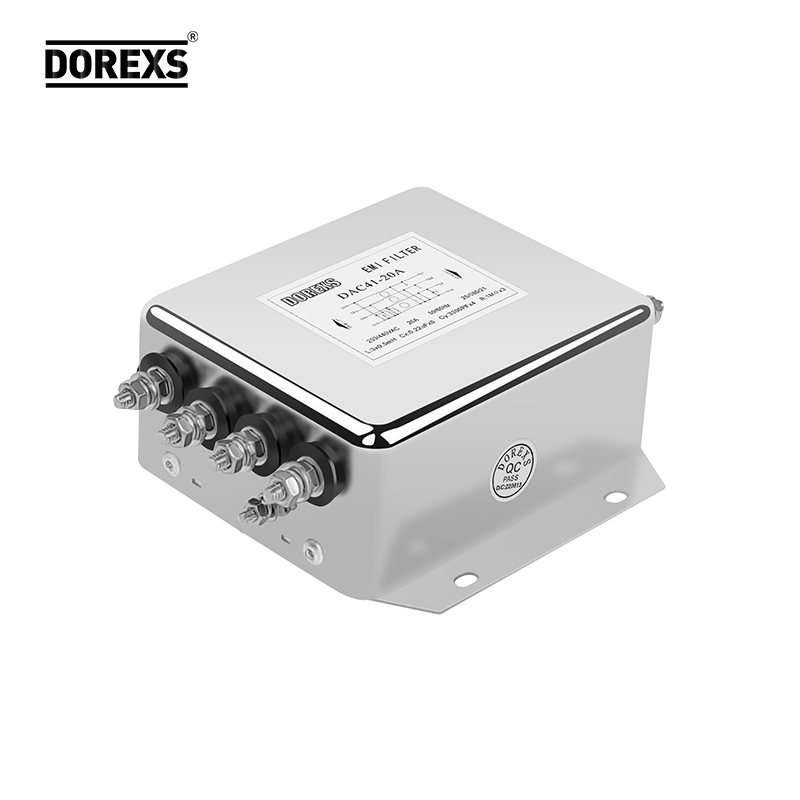
The choice between single-phase and three-phase filter configurations often hinges on the nature of the load and the level of power quality required. Single-phase filters are straightforward to integrate into residential or light commercial systems, where simplicity and cost take precedence. They handle lower power levels and typically address issues like line harmonics or voltage spikes without demanding complex control. However, their filtering capability is limited by the single current path, making them less effective at canceling certain harmonic orders that require phase interaction.
Three-phase filter topologies, on the other hand, exploit the inherent symmetry of a three-wire or four-wire system to achieve deeper attenuation across a broader spectrum. By using combinations of inductors and capacitors arranged in delta or wye configurations, these filters can target zero-sequence and negative-sequence harmonics that single-phase designs simply cannot touch. Industrial drives, large rectifiers, and motor control centers benefit from this approach because it reduces common-mode noise and improves overall system efficiency. The trade-off is a more intricate design and higher component count, but for high-power environments, the benefit is substantial.
Another practical distinction lies in neutral current handling. In three-phase systems with nonlinear loads, triplen harmonics accumulate in the neutral conductor, creating overheating risks. A three-phase filter with a neutral connection can divert or cancel these currents, whereas a single-phase filter would need to be oversized for each phase individually, resulting in poor cost-performance. Selecting the right topology is thus less about absolute superiority and more about matching the filter architecture to the specific electrical environment, loading pattern, and harmonic profile present.
Feedthrough Capacitors for Enclosure Shielding
The real bottleneck in enclosure shielding isn't the metal walls themselves—it's the penetrations. Every cable, connector, or wire passing through the enclosure creates a path for high-frequency interference to leak in or out. Feedthrough capacitors solve this by making the filter part of the penetration point. The capacitor body threads or mounts directly into the shield wall, so the filtering element sits exactly where the conductor crosses the barrier. This removes the long lead inductance that makes ordinary bypass capacitors ineffective at higher frequencies.
Getting the installation right matters more than the capacitor's nominal value. A feedthrough capacitor must bond to the enclosure with low impedance around its entire circumference. Screw threads or soldered flanges provide the mechanical integrity, but even a small gap can let RF current find a way around the filter. In practice, designers often add a conductive gasket or use a bulkhead mount that presses the capacitor firmly against the shield. The choice of capacitance depends on the noise spectrum: larger values give more attenuation below the self-resonant frequency, while a lower-value part in parallel may be needed to cover higher bands.
When done properly, feedthrough capacitors turn enclosure walls from simple Faraday cages into active filtering panels. This is especially useful in mixed-signal systems where digital switching noise must not reach sensitive analog stages, or in equipment that must pass stringent EMC tests without adding bulky external filters. The capacitors quietly maintain shield integrity at every wire exit, which often proves more effective than adding more grounding straps or thicker metal.
Medical-Grade Power Line Filtering Beyond the Standards
Meeting IEC 60601 leakage current limits is a baseline, not a guarantee of clean power in a real hospital. The standard assumes a relatively tame mains environment, but operating rooms and intensive care units are full of devices that inject broadband noise back onto the line—surgical lasers, MRI chillers, variable-frequency drives in HVAC systems. A filter that simply passes compliance testing may still allow enough conducted emissions through to degrade the signal-to-noise ratio of an ECG or interfere with a ventilator's sensor front end.
Beyond the standards, medical-grade filtering has to account for the odd mix of old and new infrastructure found in many facilities. Wiring that predates modern grounding practices, shared neutrals, and emergency generator changeovers create transients that don't appear in any test waveform. Effective designs therefore widen the attenuation bandwidth well past the typical 150 kHz starting point and add staged common-mode and differential-mode rejection, while keeping earth leakage low enough for patient-connected equipment.
There is also a reliability angle that standards don't fully capture. A filter inside a medical cart or wall-mounted monitor may sit close to heat sources or experience repeated inrush cycles. Components chosen only to pass a one-time test can degrade, changing the filter's resonant point and eventually letting noise through. Designers who push beyond the standards select capacitors and inductors with derated voltage and temperature margins, and they verify performance under sustained full load rather than just at the moment of certification.
Avoiding Overfiltering While Meeting Conducted Emissions Limits
Meeting conducted emissions limits often pushes designers toward aggressive filtering, but excessive attenuation can degrade power integrity and introduce instability. The key is to target the specific frequency bands where emissions exceed the limit rather than applying a broad low-pass approach. By measuring the actual noise spectrum and identifying whether the dominant component is differential-mode or common-mode, you can select filter topologies that add just enough loss at the offending frequencies while leaving the rest of the passband relatively untouched.
Another practical lever is impedance control. A filter's insertion loss depends heavily on source and load impedances, which vary with frequency in real converters. Instead of stacking multiple LC stages that can create resonant peaks and ringing, try adjusting the damping or moving the corner frequency slightly above the first harmonic that needs suppression. Sometimes a small ferrite bead or a carefully placed bypass capacitor will achieve compliance without the bulky, overdesigned filter that eats into efficiency and board space.
Finally, validate the design with a spectrum analyzer or pre-compliance scan while the device operates in its worst-case load condition. Adjust component values iteratively, watching not only the peak emissions but also the margin at adjacent frequencies. This approach helps you stop filtering as soon as the limit is met, avoiding the common mistake of adding unnecessary attenuation that only creates new resonances or reduces the reliability of the power delivery network.
Grounding and Mounting Practices That Make or Break Filter Performance
A filter's datasheet might promise 40 dB of attenuation, but bolt it to a poorly prepped chassis and you'll be lucky to see half that. The ground path isn't just a wire going to a lug—it's the entire mounting surface. Anodized or powder-coated panels act as insulators unless you remove the finish under the filter's flange. Even then, a single screw in the center of the housing often leaves the outer edges floating, creating a slot antenna at exactly the frequencies you're trying to kill. Use flat, bare-metal contact across the full footprint, and torque the fasteners in a star pattern to avoid warping the base.
Mounting orientation also sneaks into the math. Input and output leads routed too close together, or worse, tie-wrapped in parallel, let noise bypass the filter through stray capacitance. Keep the input wiring short and shielded, and run the output away at a right angle. If you're mounting the filter through a bulkhead, the case-to-panel joint must be continuous—no plastic washers, no rubber gaskets, no paint. A single ohm of resistance across that seam can turn a 60 dB filter into a 25 dB one, because the return current takes the path of least impedance right around your carefully chosen component.
Don't overlook what happens downstream. A filter mounted beautifully on a cold, bare chassis still fails if the load side radiates into adjacent cables. Twist the output pairs, keep them off the enclosure walls, and avoid looping any excess length into a coil. The filter's performance is only as good as the installation it lives in—grounding and mounting aren't afterthoughts, they're the first stage of the design.
FAQ
The reliable ones survive the mismatch between the 50-ohm lab setup and the real impedance of your power lines. They maintain insertion loss across the 150 kHz to 30 MHz band even when the source and load aren't resistive, use Y capacitors sized for the actual leakage current budget in your product, and don't fall apart when the common-mode choke saturates under heavy load. If a vendor can't give you S-parameter or attenuation curves at several load impedances, treat it as a red flag.
Because the filter's internal inductance and capacitance only behave as expected when the interfering current has a clear return path to the noise source. In many installations, the filter is bolted to a painted or anodized chassis, so the Y capacitors can't shunt common-mode noise to ground effectively. The resulting loop includes cable inductance and chassis seams, which adds another 10–20 dB of noise between the filter and the connector. A bare metal bond within a few millimeters of the input socket usually fixes more than swapping to a higher-priced filter.
Start with the expected noise profile, not just the wattage. A single-stage filter typically gives 30–50 dB attenuation in the mid-band, which suits supplies with low dv/dt switching nodes and short unshielded cables. If your converter uses hard-switched MOSFETs or the leads to the load exceed about 10 cm, go two-stage: the extra inductor-capacitor network flattens the resonance peaks that make single-stage units roll off early. Also verify the second stage doesn't push the Y-cap leakage above your standard's limit, such as 0.5 mA for many medical or handheld devices.
For six-switch inverter drives, a two-stage LC or LCL topology with a damping resistor across the first inductor is often the best balance. It suppresses both the differential-mode switching ripple around the PWM frequency and the common-mode currents returning through the motor bearing. The damping resistor prevents the filter from ringing at its corner frequency when the drive suddenly changes duty cycle. You also want the common-mode choke wound on a high-permeability nanocrystalline core so it holds impedance above a few megahertz where the filter's ceramic capacitors become inductive.
That depends on how much current your cable carries and where the noise is generated. A ferrite bead clamped on a wire can add 20–80 ohms at 100 MHz, which is enough for data lines and low-current signal cables. But on power lines carrying several amps, a single bead saturates and its impedance collapses to near zero, so it won't stop conducted emissions in the 30–200 MHz range. Use a proper LC filter with a split-winding common-mode choke for power paths; the choke presents 200–2000 ohms over a broad band and doesn't depend on the field from one conductor alone.
The most common one is using a long green/yellow wire from the filter case to a chassis stud several centimeters away. At 30 MHz that wire has over 20 ohms of inductive reactance, so the filter's Y capacitors can't return noise to the source. Another is mounting the filter on a painted panel and relying on the screws alone for contact; galvanic corrosion and paint thickness vary too much. A clean, unpainted mounting surface with a conductive gasket or multiple short screws every few centimeters gives the filter a low-inductance bond. Also keep the input and output leads separated—bundling them lets high-frequency noise couple past the filter through stray capacitance.
When the required attenuation, leakage current, or physical shape doesn't match standard catalogs at your operating voltage. For example, a 690 V AC drive used in a medical cart under 100 µA leakage limits will rarely find a commodity filter that satisfies both. Custom designs let you place the Y capacitors on the line side only, choose a toroidal core with minimal parasitic capacitance, and integrate the filter into the connector housing so the filtered and unfiltered leads never share a route. The development cost is usually recovered after a few hundred units if the alternative is failing a test chamber run and delaying the launch.
Conclusion
Reliable electromagnetic compatibility rarely hinges on one component; it depends on how filtering choices interact with the circuit's return path and enclosure. Common-mode chokes remain the quiet workhorses for cleaning up signal return lines, suppressing currents that would otherwise travel together and radiate. The decision between single-phase and three-phase topologies shapes both footprint and attenuation—single-phase filters fit smaller equipment, while three-phase versions handle higher power but demand more careful balance and insertion loss. Feedthrough capacitors also prove invaluable where cables enter shielded enclosures, shunting high-frequency noise at the boundary rather than letting it propagate inside or out.
Medical installations illustrate how far filtering can go beyond baseline compliance; these designs often target lower leakage current and stricter isolation even when generic industrial limits would pass. At the same time, chasing maximum attenuation can backfire. Overfiltering adds cost, bulk, and sometimes resonance or ground-loop headaches without meaningfully improving conducted emissions margins. The physical side is equally decisive: a filter's grounding and mounting determine whether its internal elements actually divert interference to chassis or just float above it. Low-impedance bonds, short leads, and placement close to the noise source routinely make the difference between a marginal pass and a robust margin.
Contact Us
Contact Person: Eric
Email: [email protected]
Tel/WhatsApp: 8618117837140
Website: https://www.emcdorexs.com